Misc. Project - Volvo P3 Desk Chair

Foreward

I am in the process of upgrading my desk setup as my current Ikea desk with a piece of plywood over it and a gaming chair isnt the best look in my house. Given the costs of “professional” desk chairs designed for taller people I decided to take it upon myself to build one from a Volvo seat. The project was actually much easier than I thought, and If I had to build another there are a few changes I would make.

Prerequisites

Tools you will need:

  • Angle grinder

  • Bench grinder (to remove burrs) or grind stone for angle grinder

  • Wire strippers

  • Misc. Torx and metric sockets

  • Flat blade screwdriver

  • Straight blade pick (I use the $1 ones from Harbor Freight)

  • Drill and 1/4inch drill bits (you can use whatever size you like, 1/4 was easy and fit through the stock frame holes)

  • Paint (I used STEELIT)

Items to purchase:

  • Volvo P3 seat. This can come from any model, the bases are all the same. Heated seats can be found in most models, heated and cooled seats can often be found in S80s.

  • 120V AC to 12V DC (5 Amp) Power Brick

  • Desk chair with basic base. Some desk chairs have multiple adjustments and plastic bases. I went with the most basic, free desk chair I could find on Marketplace. You want to also find one with the lowest rise you can, as the base of the car seat adds significant height which shorter people may find uncomfortable.

  • 1/4in. thick steel bar stock / rectangular steel tube. I will touch more on this in the build details, however Stock Car Steel and Aluminum can cut and ship any size of steel you need for your projects without needing to visit a mill or buy huge pieces of steel!

Build Process

I started this build with the seat! These are relatively easy to find depending on where you are in the country. I went to a local DIY pull-a-part junkyard and paid $40 for my seat. The seats are held into the car with 4 bolts under plastic covers. I then used snips to cut the wires going to the harness of the seat, so I had wires to work with. The seatbelt an be unbolted from the seat frame, or in my case I just cut the seatbelt with my snips since I wasnt going to need it. This seat was not heated or cooled, so I will not be going into adding controls for those functions.

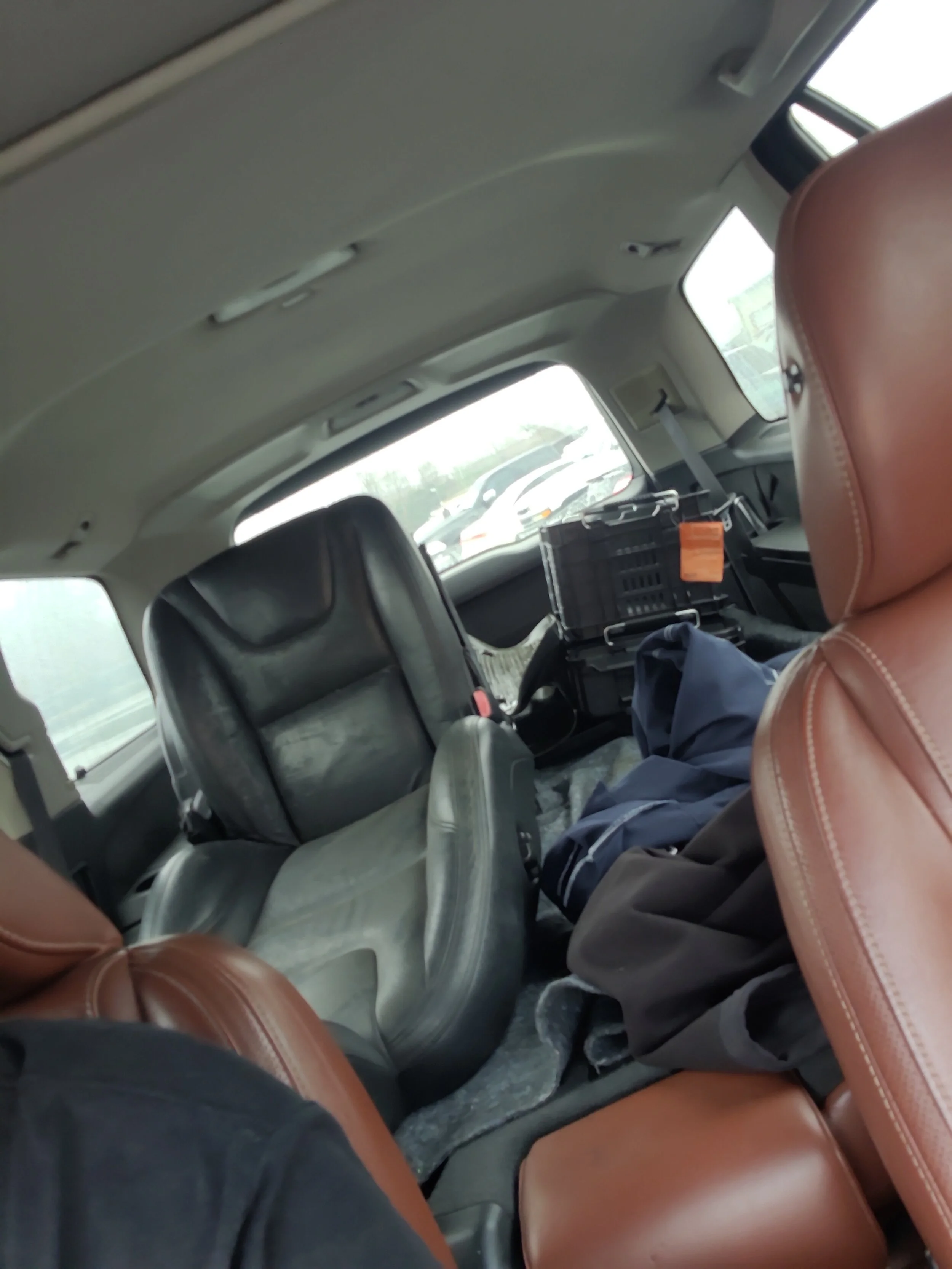
With the seat loaded up in my XC90 I headed back home to start prepping the chair for minor modifications.

I will be reusing this image, but the harness bolts into the chairs female harness, the wires usually come wrapped in tesa tape which I removed. I kept about 8 inches of pigtail harness.

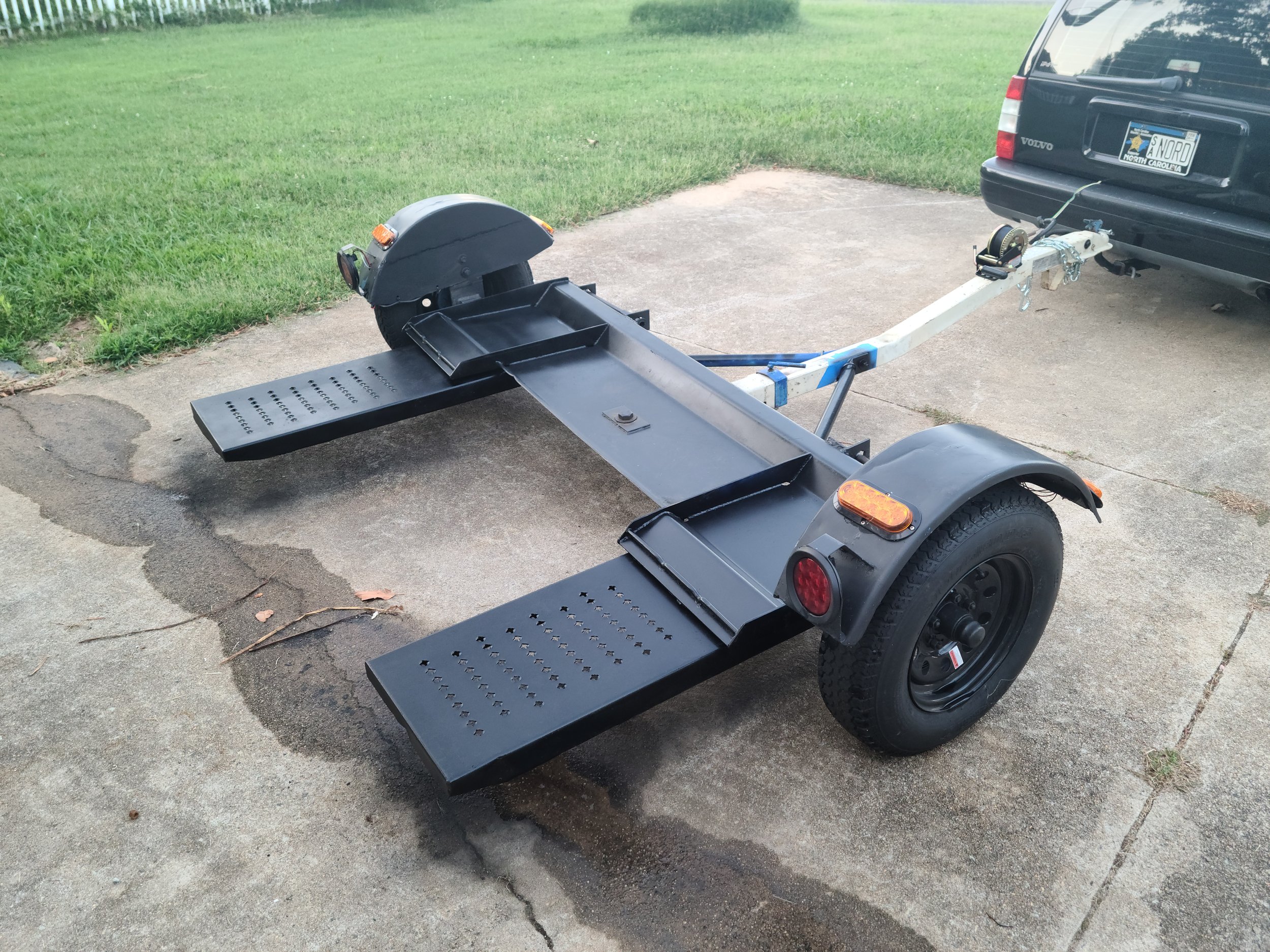
With the seat now removed from the car, the first modification is making the rails completely flat. Each end has a bracket that is welded onto the slider so it can bolt into the car. With my design I needed these out of the way, leaving a perfectly flat rail on each side of the seat.

FOR VISUAL REPRESENTATION, THE SEAT DOES NOT NEED TO BE REMOVED FROM THE RAILS

I didnt take any of my own photos for this project (so I am using this photo of P2 rails which are close). There are brackets on each corner that I used my angle grinder to cut off from the rails. These only take a few minutes to cut through and make the bottom of the seat perfectly flat.

Once I had this done, I moved onto testing and fabricating the electronics to make the power functions work. On the P3, this is very easy and consists of a 12v power, a 12v signal wire, and a ground. I would consult the Volvo wiring diagram for your own seat to confirm which wires are needed, so for this case this applies to all 2011+ S60s (and probably V60s).

Here is the diagram I followed with my notes on what you need:

74/31 is the 20 pin connector that runs from the car to the seat. The only 3 pins you need to worry about on the car side of the harness are pins 14, 15, and 16.

Pin 14: Blue / White is a signal wire from the CEM, this is a signal to the Stop Logic to allow the seat to move. Connect 12V to this wire.

Pin 15: Brown / Red is 12V power to the seat control module (3/27). Connect 12V to this wire.

Pin 16: Black / Green: This is ground for the module.

A side note regarding the other pins, SRS module, and air bags:

There is some concern by some that there is a danger in not removing the air bag from the side of the seat. The route I went to avoid incidents was to remove any and all wiring in the pigtail going to these modules. All of the pins outside of the 3 listed above can be removed, and is why the small straight pick is listed in the parts list. You can remove the small red caps from each pin and use the pick to lift the clip and slide the pin end out. Additionally, the airbag firing system needs a signal from the OWS or Occupant Weight Sensor. Going off the wiring diagram, if the OWS does not have power, even if power was sent to the airbag firing system it would not deploy since it needs the circuit completed by the OWS signal.

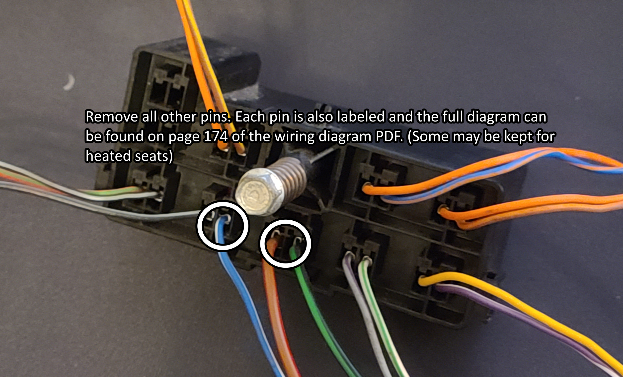
Be sure to remove the black/grey cable next to the white/blue cable as it is part of the airbag firing system!

Now you may be asking yourself well how do I apply 12V to these wires when the walls in my house put out 120V AC? Well for that we need the cheap adapter brick I linked at the top of the page. The unit I bought came with a barrel jack to screw terminal adapter which we will connect the 3 wires from out pigtail into.

I trimmed about 1/2in. from the end of each wire with my wire strippers, and twisted the 2 positive wires together at their end before inserting them into the connector. I put some electrical tape over everything before tucking it up into the seat just for extra protection. The power brick I then attached under the seat with some zip ties and tucked all the wires away.

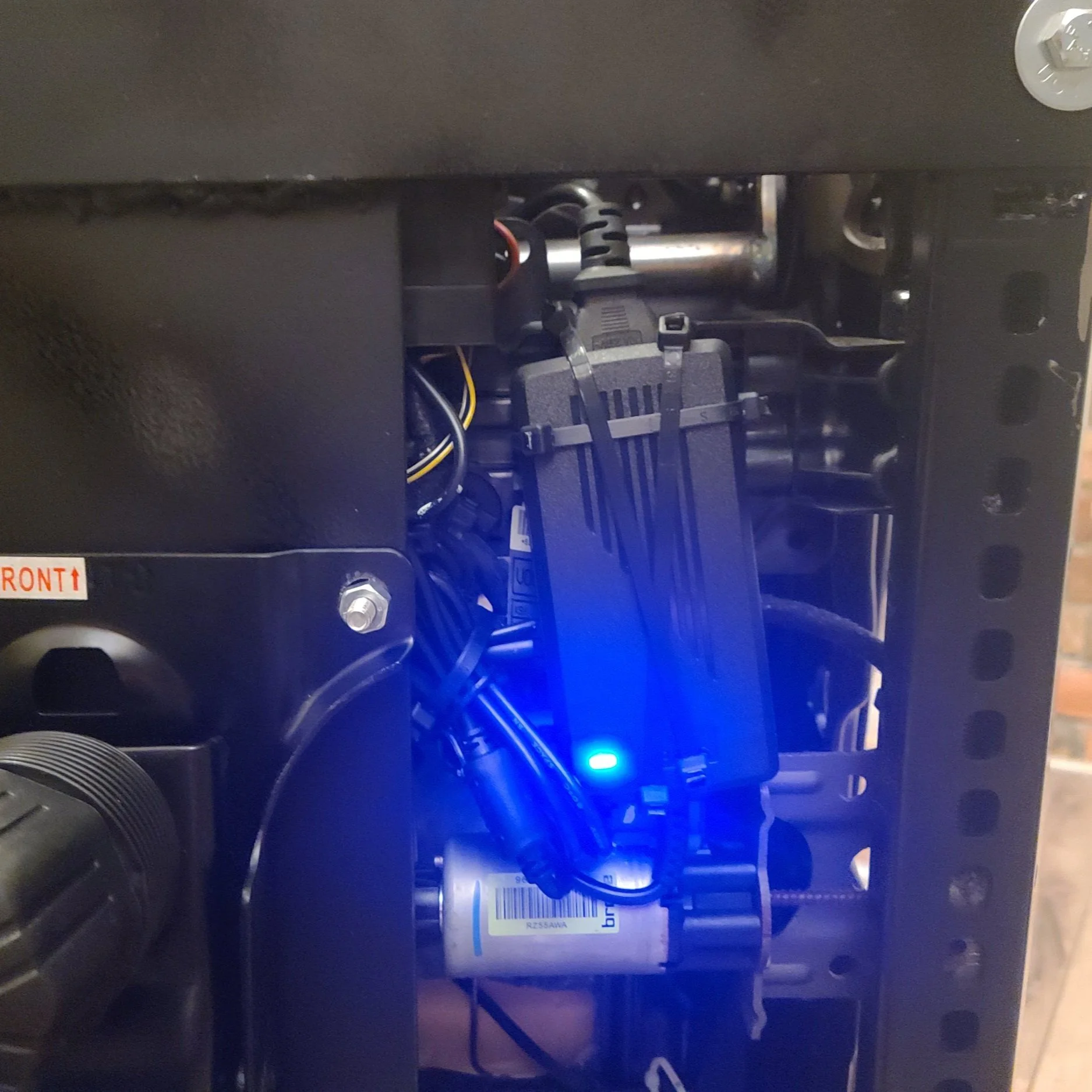
The power brick, zip tied under the chair inside the original seats rails with the other components.

The de-pinned connector to the seat.

With the electrical fully sorted, I then turned my attention to mounting the seat to the rolling chair base. I made sure to pick a donor office chair that had minimal adjustment points, and a standard 4 bolt base. Some higher end chairs have multiple pivot points and more complicated bases. I used a piece of ~8inch wide by 1/4inch thick steel flat bar. (Measure your base width before buying material) I went with what I had on hand at work in our scrap bins, otherwise I think I would have gone wider for stability. I then measured the distance between the rails both front and back and cut two more pieces of 2inch by 1/4inch steel flat bar to make my cross members. I mocked everything up with the seat sitting on the metal and the metal on the chair base so I could line everything up properly and make marks on where I needed to drill mounting holes and where the cross bars would need to sit. I did not do any crazy measurements here, just got everything looking “right” and marked parts with a paint pen so I could disassemble and bolt / weld everything together.

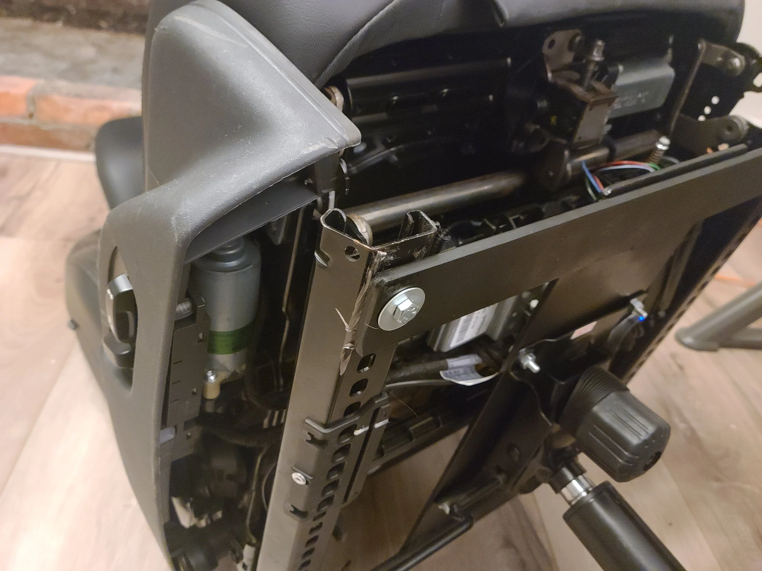
I (poorly) welded my brackets, however bolts could also be used to hold the cross members in place.

Here is the bracket mid construction. I still needed to drill the holes for the rails to bolt to, and I gave it a coat of flat black STEELIT paint. I also ended up flipping the bracket over in installation to lower the seat rails a bit to buy myself some lower seating position. Like I have previously mentioned these chairs sit very high compared to a standard chair due to all the motors underneath them, so choose your base chair wisely.

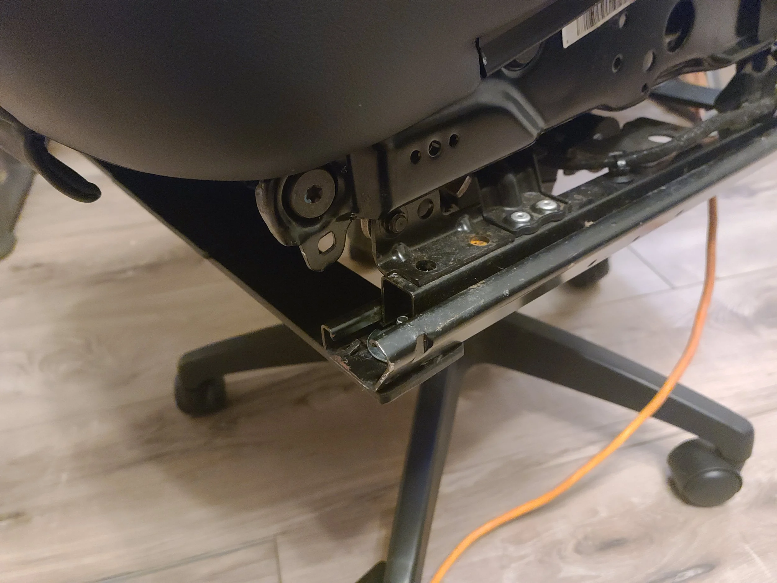
All of the hardware used was 1/4 inch bolts from Lowes. I also used some stacked washers on the front bolts for the frame rail since the hole for the original bolts in the car are quite large.

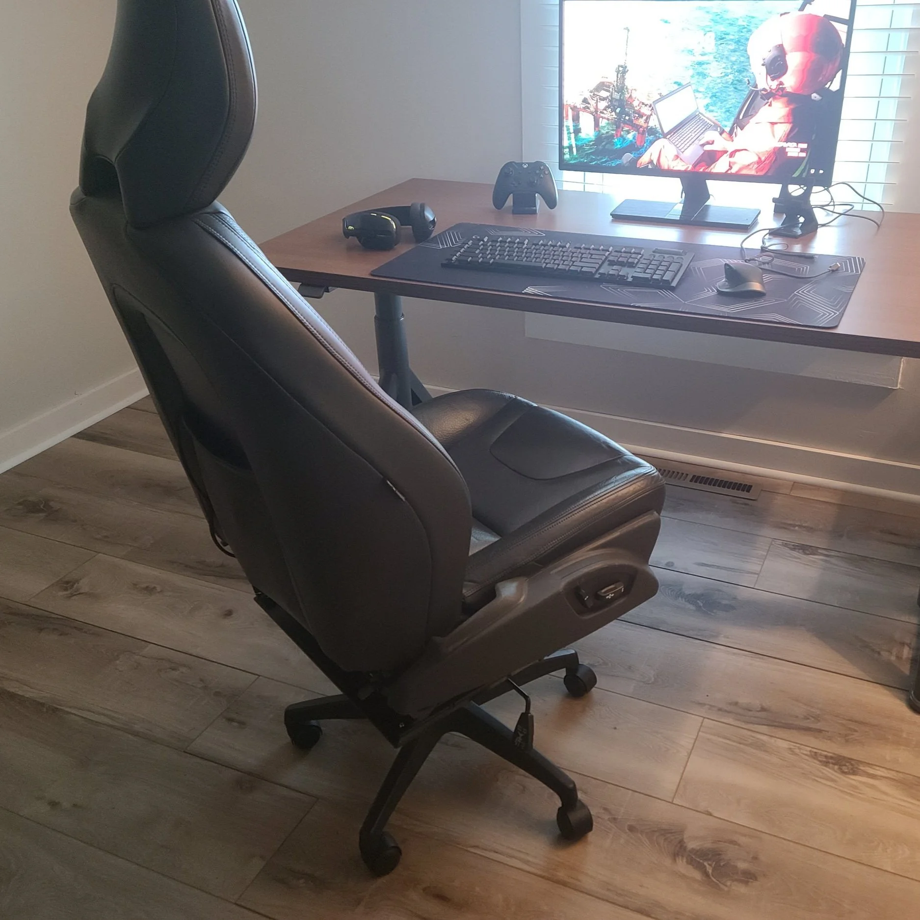
The last thing I did was run an 8ft "designer” extension cord out of the back of the seat from the power adapter and left all the slack in the seat back pocket. This will allow me to plug it into my desk without having to run the long extension cord from my wall to the chair, and it can be neatly tucked away inside the seat back pocket when not in use.

Conclusion:

There are a few things I would change about this build. The first thing is that I would have used a mild rectangle steel square tube instead of flat bar for the cross members. With the way I flipped the bracket upside down this would NOT have added any extra height but would have added some extra stability side to side. Additionally a higher quality base would have been nice to use as there is some play with the sheer amount of weight its now carrying. Lastly, I still plan on adding arm rests using some generic bolt on arm rests from Amazon, I just need to get around to ordering them and possibly adding some more brackets to allow them to attach where I need to.

I hope you all enjoyed this little project, it completely blew up on Reddit which I did not expect! For a 2 day project that I sort of made up as I went I am very pleased so far with the outcome. If you have any suggestions please feel free to leave them down in the comments.

The Definitive P2 XC90 External Transmission Cooler Writeup

FOREWORD

If you have a 2007+ V8 (or 3.2) Volvo XC90 and plan on towing, one of the first things youll find is pages upon pages of forum threads talking about transmission fluid and cooling. This guide, I hope, will serve as a definitive guide for someone looking to install an OEM transmission cooler for cheap!

Please note: If your car was equipped with the Tow Package from the factory. This cooler will have already been installed.

PREREQUISITES

For this project you will need the following tools and materials:

  • Impact gun OR wrench + socket set with various metric sizes.

  • Various torx bits.

  • Various phillips and flat blade screwdrivers.

  • Trim / Bone tool (non-marring scrappers also work).

  • Harbor Freight U-Clip and Screw Pack

    • Not needed if necessary u-clip is removed from donor vehicle.

  • Harbor Freight Automotive Fastener Pack

  • Long Reach Funnel (I used a specific one from IPD designed for reaching transmission fill holes).

  • Hose Clamps

  • Idemitsu TLS-LV Automatic Transmission Fluid

  • 3/8ths Hose to -6 AN Male Fitting

  • 3/8ths Hose to -6 AN Female Fitting

    • Optionally a 3/8ths Barb Fitting can be used, however I went with AN fittings since it makes it easier to separate the lines to do fluid changes.

  • 5 or 10 Quart Measuring Buckets (Easy to find at almost any hardware store).

  • OEM Volvo XC90 Transmission Cooler with lines.

    • Things to note: You can easily find these on all T6 models as they came standard from the factory with this cooler. They will have one line that runs from the top of the radiator cooler down to the unit, unclip this from the top and leave clipped in at the bottom. The return line from the external cooler to the transmission is extremely hard to unbolt, so we will cut this line as far down as possible towards the transmission.

    • I found that squeezing the clips and gently twisting the hose allowed it to pop free easily without a single broken clip anywhere along the install and test fitting process.

    • This unit can be purchased new from Volvo here, however this is expensive and also requires unbolting the lines from the transmission to install. the replacement return line from the cooler.

Guide

Throughout this guide, I may make references (and link to) other guides on Swedespeed and other various forums. This will be done to save myself time, and often these guides have better photos for the task at hand. This guide is also being written with the assumption that the end user has basic mechanical knowledge, and is familiar with their vehicle to some extent. This is NOT a hard project, and can be done using almost all basic hand tools. Additionally, if the parts mentioned have been pulled from a junkyard vehicle, much of the process is the same, just in reverse. This guide may help you in removal of the donor unit if followed in reverse order.

To start, lets begin with removing the front bumper of the vehicle. I followed this guide here. (NOTE: Do NOT follow the guides way of removing the headlights, there is a main harness connector further down from the lamps that can be disconnected to remove the headlights without unplugging the harness from the unit itself!) I used a strong non-marring plastic tool to pop the corner clips close to the fender, they were very strong! And helps to work at them slowly, releasing a tab one at a time. The two clips under the bumper were destroyed in my process (which is why I bought the cheap set of automotive clips from Harbor Freight). With the bumper off you should be left with this:

Next we will remove the lower metal skid plate to give us better access to the hoses and bolts. I used a deep socket for these as they have 3 bolts on each side, with one being up inside the front structure of the car.

With this skid plate out of the way you will have easy access to the transmission lines as well as the mounting points for the cooler. Lets begin mounting the cooler in place without the hardlines installed. You need to remove the 2 bolts that hold up the power steering fluid cooler. The external transmission cooler sandwiches between the various radiators and coolers, and uses the same bolts as the PS cooler.

Now that the cooler is mounted in place, you can disconnect the return line from the top of the radiator-integrated ATF cooler. The diagram below shows how the new lines will be run.

This diagram shows the flow of fluid as it completes its loop out of the transmission and into the coolers. Top is stock, bottom is the route with the tow package / cooler.

We can now focus on prepping our modified return line that will bring the ATF fluid from the external cooler back into the transmission. This is where the AN fittings I used come into play. I chose AN fittings due to their availability, as well as ability to hold fluids at various temp ranges and pressures. This also allows me to disconnect the lines at any point for a fluid flush without having to remove any hose clamps. I added a 3/8ths barb to -6 AN Female fitting to the cut off end of the return line that will go out of the external cooler and into the transmission.

Now we can connect the two lines to the external cooler. The inlet hose and the outlet (return) line. We are going to use the unterminated return line as a drain line for doing the ATF flush.

The two brackets on the cooler lines should line up together, and there is only one way for them to sit next to each other. This is where you will need the u-clip and screw, as it holds these two brackets to the plastic mounting point on the radiator assembly as pictured above.

While the system was apart this is the perfect time for an ATF flush. The external cooler adds extra capacity to the system, so new fluid is needed anyways. I followed this guide on Swedespeed, but instead of using a hose out of the outlet of the built in radiator cooler, I bent the outlet hose of the external cooler down into a bucket. I did 2.5 liters at a time, as a lot of fluid gets “stuck” in the torque converter when its running.

https://www.swedespeed.com/threads/how-to-xc90-6-speed-transmission-fluid-flush.204760/

Once I was happy with the level of fluid in the system, I went to the last modification step which is cutting the OEM return line to add my AN fitting. if you refer to the diagram earlier in the post you will know that we have to connect the outlet line of the external cooler to the original return line to the transmission. For this I cut the line fairly close to the metal end, and added a 3/8ths barb to -6AN Male fitting.

My hose clamp on the male end wound up over some of the hex of the fitting but it did not affect the intall.

You can use a standard wrench to connect these, or a specific AN wrench. Either way, with the two ends threaded together we now have a complete loop of the system. Make sure to put the car in reverse and drive a few times to make sure your ATF fluid level is okay. Add more if needed.

With this all done it is time to do all the steps we took in disassembling the car but in reverse. Adding the skid plate back, then the bumper and headlights. You have now installed an OEM cooler for pennies on the dollar compared to buying it new or having a shop or dealer install it for you!

As always, if there is anything you think I missed, or any recommendations please feel free to leave them in the comments or share your install process.

TFT Display with P3Tool Guide

Just writing that blog title filled me with a sense of dread. The TFT cluster swap is a topic so thoroughly discussed on the forums that I am scared to even open that can of worms on this website. Not only is it a slightly complicated mess, but often when I do write ups I try to be as technical and cover as much of the topic as possible meaning this could turn into a LONG post. So buckle up cause this is gonna be a nerdy one


Introduction

The TFT cluster swap is a common modification for the P3 chassis Volvos to update the original “watch face” style gauge cluster (also referred to as a DIM, or Drivers Information Module) to the facelifted digital style found in the 2014+ models. This applies to all P3 chassis cars like the V70, S80, XC70, XC60, and S60. The V60 is left off this list as it was only sold in the US from the 2014 MY onwards and as such already has the TFT display.

The digital cluster is preferred since it adds back in some information for the driver like engine temps, as well as offering different display themes (some of which can be modded and changed further with editing tools). Since it shares the same shell as the pre-facelift DIM, they are a near “plug and play” swap when it comes to physically installing it into the car.

These updated DIMs can often be found on eBay and now even in junkyards as these cars become older and sent to dismantlers.


Prerequisites, Parts, and Supplies

Before we start taking stuff apart and soldering wires, lets get all of the items we are going to need / use for this cluster swap.

Hardware

  • Windows PC laptop

  • Volvo DICE unit

  • Battery tender

  • 2014+ TFT Display (multiple part numbers available*)

  • 2 Volvo cluster pins (I took these from a P1 cluster, more on this later).

  • Soldering Iron

  • Torx Bits

  • Pick / Pinning Tool

  • 20 AWG Wire

  • (Optional) Replacement Instrument Panel Glass Lens (31376800)

Software

  • Cars CEM PIN Unlocked

  • Up to date DICE drivers

  • P3Tool w/ active license

And here is the part where I would have a well written and photographed step-by-step instructions on the rest of the process, however…


The Swap

I started working on this article in January of 2023, it is now mid August of 2023 and I have still to “finalize” this swap. That being said there are some updates now later in the year, and I do in fact have the cluster installed. In the August update of P3Tool Johnny added full functionality to do the TFT swap and even included tools to rewrite software on the TFT to better get them to work on various models. I did not end up taking photos of my process for the install, luckily this is a very well known process and there are multiple guides online you can follow to do the wiring and physical install of the cluster.

The TFT I refurbished is a V2 model, these can be identified by the additional venting on the rear.

The “V1” Model without venting

“V2” Model with Venting

“V3” Model only found in very late model XC60s

The TFTs got progressively better with the later model years, with slightly faster CPUs and slight quality of life updates. Any of these can be used as they are all the same size and use the same plug.

I followed all the instructions online for the hardware side of things, taping into the two wires from the ODB2 port, etc. Got the cluster installed and went to work in P3tool. This is where I will share how my install went and the changes I needed to make to ensure everything was working.

First we need to set some parameters, these are in parameter number order so some may not be applicable or wanted for your install:

  1. P#013: Screen Skins

    • 0x04 = R-Design

  2. P#040: DIM Type

    • 0x02 = DIM Type Basic LED

  3. P#101: TPMS

    • 0x01 = Without TPMS

  4. P#112: Indirect TPMS

    • 0x01 = Without indirect TPMS

  5. P#247: Fueltank Sensors

    • 0x01 = Fueltank, 1 sensor

The DIM type change is required, along with the Indirect TPMS and Fuel Tank Sensors. I have TPMS disabled on my car since I am using wheels from a V90 without TPMS sensors in the valve stem. Some of the TFT clusters come from cars that do not use TPMS but rather iTPMS which measures the rolling diameter of the wheels to determine air pressure. I had a permanent TPMS light on the TFT until I switched parameter 112 off Undefined. Additionally the TFT uses data from parameter 247 which is 1 sensor for FWD, and 2 sensors for AWD. Without this, the fuel gauge will either not read or read improperly. (I am still working through testing this.)

Next, lets move over to the new P3 DIM tab in P3Tool.

Here we will begin to prep the old cluster for removal (they can function fine with all of these parameter changes made, and even the extra wires into the plug).

Here is the step by step instruction:

  1. Read Milage from original DIM

  2. Read EEPROM from original DIM

  3. Full Backup of original DIM

  4. Install new TFT DIM

  5. Full Backup of TFT DIM

  6. Select Fuel Tank Model (Select based on FWD or AWD)

  7. Select Model Year of your car

  8. Select Base Flash

  9. Click Write Flash

The DIM will go blank as the data is being written to it. Once it is done, it should light up with everything working. Make sure to reset the SRL and set the Time before unplugging as these can not be done without Sensus (in models without Sensus center screen).

Initially configured before fixing the fuel gauge.

Changing the fuel tank parameter.

The config and guide here should work for all 3.2 V70s in the US as they are all the same spec. Keep in mind this is just the first revision of the software so expect some hang ups. Always make sure to make backups and keep your original DIM handy as there are reported cases of some TFT clusters becoming corrupted during the flashing process.

Facility Upgrades and Updates Pt. 2 - Tow Dolly

One of the biggest things needed for the business since I started was a way to tow cars. My Volvo 960 has always made a great tow vehicle, albeit a little slow. Now that I had the space, it was time to spend the money and buy a tow dolly to bring cars back for parting out.

Finding a tow dolly for cheap is no easy process. They tend to hold their value very well, as they really only exist in 2 states. Working and not working. Additionally there is a buyer at almost any price point for a dolly, mostly people trying to rent them out or start a towing service. The one I bought was a last minute deal, having to do most of the drive during the cold night hours of early March.

(Its worth noting I started writing this in March, and it is currently August as I am finishing it. Sorry!)

The first issue I had to tackle was actually getting the trailer lighting to work. The wiring was clearly redone multiple times in its lifetime, and was a absolute disaster of home grade wires and twist connectors. Additionally, the plug at the end was an ancient 5 pin design that wasn’t going to work at all with the 4 pin connector on my Volvo 960.

The crusty original wiring.

The trailer had clearly been sitting for some time in the previous owners property. Most surfaces had a thick layer of lichen and dirt. I trimmed the wiring back to just the black and red running through the chassis of the trailer and set about removing each fender for its new lighting. Everything already on the trailer was scrapped. Wiring, lights, everything. I wanted to make sure the new system was all LED for better reliability and brightness. On top of all that, I hated the goofy blue and white paint job the dolly had come from the factory with and I planned a full repaint.

A coat of STEEL-IT applied inside the barn. The cold weather outside forced me to work inside for a decent amount of time.

For each fender I planned on a new brake / turn lamp along with 2 orange markers that would also follow the light pattern of the brake light.

I want to note that this setup is not optimal but with the two wire system, I could not separate the functions as the “brake” and “turn” are the same signal. The orange marker lamps allow oncoming vehicles to see my turn signals from the front due to the wide width of the dolly, but this also means they illuminate when braking.

Bench testing with a repurposed PC power supply.

New holes were drilled for wiring, and the lights were all self-tappered into the very thick metal of the fenders. Each one of these fenders weighs at least ~20+lbs, so an upgrade to plastic fenders will possibly be in this dollys future. I am not totally happy with the wiring management and the inside of the fender leaves very few options on where to run them. This lead to an issue with one wire being rubbed on the tire during use which I was able to remedy.

The deck and fenders painted.

Most importantly new wheels and tires were added. I sprung for some premounted black trailer wheels which I thought looked pretty good and cleaned up the look significantly. While the trailer was still a little ugly, it was time for its maiden voyage. Some new wheel tie downs and some grease in the hubs and it was off to the races.

6 hour round trip to pick up a drivetrain-less Volvo 740 to part out.

This first trip went off without a hitch. The trailer did great, and was surprisingly tame behind the 960. I did manage to lose a light on my second tow when I let this 740 off the trailer and it smacked the fender without me noticing. I was able to fix the bracket and move on, no harm no foul. As I have done a few more tows (longer distances and heavier vehicles) I have begun to add small upgrades here and there. The biggest bonus was adding a winch to the tongue. Now I should have gone with a wire cabled one over the one I bought, however after using it to pull a dead Volvo 760 turbo diesel onto the dolly, I felt that its probably good enough for the handful of uses it will get.

This winch is bolted through the frame. While it may not be as strong as welded, drilling a hole and running bolts from the hardware store through is my only option until I can afford a welding setup. The winch is from Harbor Freight, and the bolts were generic metric bolts and nuts from Lowes. They thankfully had a 4” long bolt that was a perfect fit for the application!

In preparation for its most recent tow job (the aforementioned 760 Turbo Diesel) I gave the dolly a second paint job. This time with a much stronger bed liner spray. This seemed to hold up much better, however I think the areas where the wheels sit will need a few extra coats to give them the protection I am looking for and to better hide and blue paint that comes through.

On this trip the sway from the trailer was much more noticeable when it was unloaded. This I think is in part to a fix I did on the tilt lockout system. The dolly has two locks for the tilt bed, one on the horizontal, and another that is vertical helping relieve strain from the horizontal pin. Unfortunately on this trailer that vertical clamp system is stripped out and would allow the collar to vibrate off, leading to more strain on the horizontal pin.

The collar and pin in question. Ignore the unfinished paint job.

I ended up drilling a hole into the top of the white tilt bed allowing the vertical pin to stay in place. This unfortunately means its no longer putting any pressure down on the system to sandwich the tilt system leading to more sway. I will remedy this with a D ring on the tilt bed which will be hooked to the winch when not in use. This in theory should eliminate the “lift” from the shifting deck and reduce sway.

The last upgrade I have planned is for the bearings. This lead me down a rabbit hole of wasted money and time. To give you some context almost all trailers, whether they be tow dolly’s or utility trailers use (for the most part) a standard wheel lug pattern and a standard hub ID for bearing and bearing caps. This standard is 1.98” for the ID of the hub, and a hub cover / dust boot is needed to prevent grease from flying out at speed. My trailer has none. Well it has one, but its missing parts so it may was well have none. I then spent a pretty penny on some of the best bearing covers on the market; Bearing Buddies. Well In my infinite wisdom I assumed the dolly would use the 1.98” covers. I even cross referenced this with the MasterTow website which lists their bearings having this measurement. Well lo-and-behold they arrive and they are too small. After some more mucking about, I finally break out the calipers and find the ID of my bearings is 52mm (2.047”in.). Great. That means at some point the hubs were replaced or the older models use this weird size. Additionally one of the grease zerks on one side of the axle is completely wallowed out and gone. GREAT.

The remnants of the dust boots on each side. No rubber cap at all.

The BearingBuddy installed with the new rubber protector.

With the correct size BB’s installed this trailer is ready for even more hard work and hopefully a much longer useable life. The BearingBuddies are great as the design has a grease zerk integrated into the face so extra grease can be packed behind them, helping eliminate my broken grease zerk issue.


Personal Note:

I am finally back after a long hiatus of no content. I am still working on a write up for the new TFT dashboard for the V70, I have been waiting on Johnny of PxTool to finish adding the final code to the program that allows it to read and write with a wider selection of part numbers. I have been hard at work with the business and my house, so my time to write these has been limited. I hope you all enjoy this installment, and I look forward to making some great new write ups for you all.

Facility Upgrades and Updates Pt. 1 - John Deere 165 Hydro Restoration

Its been about a year since the last “state of the union” post on the business' so here is where we stand. I have decently purchased a new house on 2.6 acres of land. This includes a 3 car garage as well as a 3 car detached building in the back. While I will likely be getting more into detail as the year goes on and the renovation process starts finishing up on certain sections, one of my first purchases for the property was a lawn tractor. Not only will the vast lawns need to be cut, but it will also allow me to easily move vehicles and trailers around the property more easily. So with the winter still in full effect and the market for a lawn mower low, I set my sights on Facebook marketplace and found a nice running mower for a decent price.


THIS….is a 1987 John Deere 165 Hydro. A 12 horsepower lawn tractor with a 38” mowing deck and fancy hydrostatic transmission. No gears here, just a lever to actuate fluid levels much like a torque converter.

Here is the first picture I took of it. Its a little dirty, but it seems to have been well cared for (for a 30 year old lawnmower) and was stored inside for most of its life so no rust or paint issues. it did have a rough running issue which the seller chalked up to a bad carb. So $500 and a firm handshake later I was the owner of a lawn mower.

Here it is after a quick wash and degrease. Still needs a deep clean but I get into that a little later. Once cleaned up I opened up the hood and went to work doing some basic fixes and replacements on key components. Unlike my Volvos, I pretty much hit this thing with the parts cannon and hoped for the best. I guess its easy to do when even the OEM parts are only a couple bucks.

New heat shrink on the loose wire.

When the mower was delivered the positive cable had completely been pulled from the eyelet bolted to the battery. This was a quick fix with some pliers and a nice new shrink tube over to clean it up visually a little as the end of the eyelet was all chewed up. New battery bolts were also installed on both the positive and negative cable replacing the randomly sized bolts. I used an SAE bolt set from harbor freight but the sizes work out right at about an 11mm which should be more than ample.

As a side note, I know that this mower will probably live out the rest of its life with me, however whenever I do a repair I always try to keep in mind that maybe someone will be working on it after me and try to make it as high quality and standardized as possible.

Probably original fuel hose.

The day before I swung by Lowes and picked up some 1/4 inch hose knowing that most of the lines on the mower would need replacing. This way I dont have to worry about leaks in the engine bay. The other two braided lines could also stand to be replaced as well, however I will wait till the end of mowing season to do this refresh.

With the hose clamps on and the OEM carb cleaned and an Amazon special carb installed. I took the mower out into the yard for its first mow test. Unfortunately, this did not last long. Ater just a couple yards of mowing with the PTO engaged, it began to lose power and stopped running in the middle of the yard. With some help, I was able to get it pushed back into the garage and I was back to the drawing board.

I decided to go back to the OEM carb as all the pieces I needed to properly restore it were finally delivered. I had a pail of Chem-Dip that I used to soak the carb for 24 hours, this allowed any deposits inside the carb to break down and become lose for a second round of carb cleaner spray. I also used some Scotch-brite scuff pads to clean the gasket surfaces of the carb and used the new gaskets from the Amazon carb. The last new piece installed was a new sparkplug. The manual for the 165 states that a Champion or NGK spark plug can be used, so of course I went with the much better NGK.

The Champion plug was all fouled and of unknown age. I also have suspicion to believe that the Chinese made replacement carburetor was running the engine too rich and possibly fouling out the plug with too much fuel. Either way, with these new / rebuilt parts installed I threw everything back together and its back off to the races for the little 12HP Kawasaki.

The next upgrade was a nice new set of front wheels. These really make the tractor pop, and the new tires should last me a long time. The only snag I ran into was with actually installing the wheels. The offset of them was slightly different than the stock wheels. Therefore once they were installed onto the axle, I just had to add 2 machine washers so that there was no side to side play on the axle. Added some grease through the zerks and they are ready for the season. I am planning on also doing the rears, however I will need to remove the tires to repaint the rims. This will allow me to also install new valve stems as the originals are slowly falling apart. (Additionally, one of the wheels has a bunch of plugs in it, and are probably in need of replacing soon anyway).

The final step for prepping the mower for the season will be to sharpen the blades. Thankfully the seller gave me an extra set of blades so I can use those on a bench grinder to practice in case I mess them up. For this I bought a harbor freight bench grinder and installed it in the barn. I will use the wire wheel side to clean up the blades, then I will coat them in STEELIT to prevent rust, then finally sharpen them with the grinder wheel.